

When a Dipole isn't Straight
Dipoles
For many of us, the first antenna we used for the HF bands was a dipole. Whether it be a G5RV or other multiband dipole, or just a single band dipole cut for a particular frequency range, the dipole we likely used was one that was fed in the middle, and hung horizontally from a tree. In this article, I’d like to challenge all of those assumptions.
Dipoles Not Fed in the Middle
The first thing to challenge our assumptions is that dipoles, wires that are connected to both the center and shield of your coax, do not need to be fed in the middle. In fact, there can be some advantages for not feeding one there.
A dipole in free-space (sufficiently away from other objects, including the Earth, such that no object has a measurable effect on it) have an impedance at the feed-point of about 72 Ohms. That’s reasonably close to 50 Ohms so no modern transceiver will complain about the difference too much (that gives you an SWR of about 1.4:1). But, the other thing about that impedance is that it is purely resistive. There is no inductive or capacitive reactance to suck up your power and reduce your signal strength.
Here’s a quick model I made of a dipole hanging in free space with 8.5-feet of #18 wire on each side (fed in the middle). My modeling program gave me the following numbers for this dipole:
Frequency 28.100 MHz
Feedpoint(1) – Z: (72.243 + i 0.531) VSWR(Zo=50 Ω): 1.4:1
Now imagine you have the wire lengths a little different from above. Instead of having 8.5-feet of wire on either side, you have 9.5-feet of wire on one side, and 7.5-feet on the other. What will happen? The dipole still behaves the same way as far as sending signals out (the pattern of the radiation doesn’t change), but the feed-point impedance will have changed from about 72 Ohms to about 100 Ohms. Here’s the results from my modeling program:
Feedpoint(1) – Z: (97.900 – i 1.103)
This shows almost 98 Ohms with just a little capacitive reactance at the feed-point. This is so close to 100 Ohms that I wonder what the SWR would look like if we were to put a 2:1 transformer there. In fact, this kind of calculation is easy: the model program does it for us if we ask. Here’s the full line of details for our 10m antenna fed slightly off-center:
Feedpoint(1) – Z: (97.900 – i 1.103) VSWR(Zo=100 Ω): 1.0:1
Wow! Now we have a perfect 1.0:1 SWR and all the same performance as the previously configured antenna!
This trick works for another off-center fed (OCF) antennas. A popular antenna is a Carolina Windom which is fed off-center so much that it requires a 9:1 transformer to bring the impedance down to 50 Ohms. This isn’t cheating, and except for the small losses you’re inevitably going to have in any transformer, this is a good solution for getting a great match.
Dipoles Don’t Need to Go Straight
The thing about dipoles is: there isn’t a lot going on near the end of a dipole. In Figure 1 you can see a “droopy dipole” a dipole with about 5.7-foot on a side, and with 3-feet of wire drooping off the end. The diagram is color-coded with the most current flowing near the yellow of the middle, and the least flowing at the ends where the color is purple. If there is no current flowing it doesn’t really matter where the wire goes (so long as it doesn’t interfere with the rest of the antenna system).
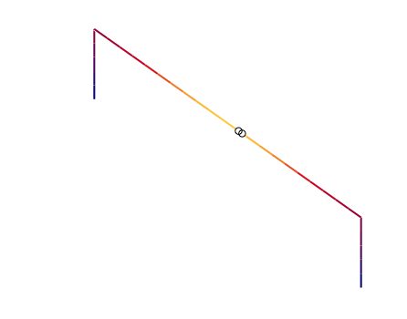
Figure 1. The Droopy Dipole
As it turns out, this 10m antenna tuned for 28.1 MHz is just a little easier to tune than it’s flattop brother. There’s my modeling program’s view of this antenna:
Feedpoint(1) – Z: (56.900 – i 2.113) VSWR(Zo=50 Ω): 1.1:1
Normally I don’t recommend looking too hard at the SWR number as it doesn’t give you a good idea of the antenna’s efficiency. But, when the reactance number is just a couple of Ohms like we have here, then why not go for a good match? And, we get one with a 1.1:1 SWR.
I’m not sure you should plan on deploying a droopy dipole to achieve these goals, but this shows that a dipole doesn’t have to go straight to be a good antenna. Droopy dipoles can be good performers, and provide a good match to your transceiver.
Dipole not in a Tree
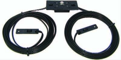
This is one of the four free-standing vertical dipoles I have in my yard. I don’t want any antenna I can’t work on from the ground (I don’t like heights, and I’m pretty sure I don’t bounce as well as when I was young). These antennas are made from aluminum and are fed in the middle. They also have a “droopy dipole” kind of design. The horizontal top and bottom elements are shown in Figure 2 are called “capacity hats” and serve the same purpose as the extra wire that droops in a droopy dipole: it makes the antenna the correct length electrically even if there isn’t much current that will ever flow through it.
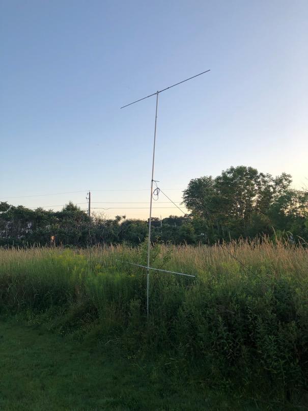
Figure 2. A Vertical Dipole for 15m
Here’s a model for an antenna like this. (I made this one up from scratch, but the model said it would work about as well). See figure 3 below.
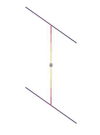
Figure 3. Model view of the Vertical Dipole
In this design, I had the dipole fed in the middle of the vertical segment with about 6-feet of pipe above and below the feed-point. The “wings” (the parts that radiate away from the vertical section) are about 3.8-feet in length. Here’s what the modeling program had to say for this antenna:
Feedpoint(1) – Z: (41.881 – i 0.078) VSWR(Zo=50 Ω): 1.2:1
The feed-point impedance is close to 50 Ohms (just a little low at about 42 Ohms), but the match is almost perfect with less than a tenth-of-an-Ohm of reactance. This is a very efficient antenna, and it has a match of 1.2:1 (SWR).
So, this antenna is fed in the middle (though you could easily design one that wasn’t!), doesn’t go straight, is positioned vertically, and isn’t hung from a tree!
I have four antennas like this for 10m, 15m, 20m, and 40m, the four top bands for an HF contest. They perform very well. (I’ve worked India on phone from the 40m antenna!)
These antennas were made by Force-12, but they are not currently available. JK Antennas are now selling the Force-12 brand, but they’ve not begun manufacturing the complete Force-12 line yet.
If you’d like to see a multi-band version of the same style of antenna, look no further than to DX Engineering‘s TW Antenna series including the 5-Band Globetrotter.
A final thought on Vertical Dipoles
Actually, I do have a dipole hung in a tree. But, it is a 12m dipole, fed in the middle, hung by one end vertically with a weight suspended at the bottom. This antenna helped me get DXCC on 12-meters a few summers ago. It is much easier to put a dipole in a tree if you only need to lift one end. I just flung a rope over the highest point I could hit, and then pulled up the dipole’s end. It was one of the easiest dipoles I’ve ever hung.
If you have a high-band (20m or above) dipole that isn’t too long, consider hanging it vertically. It is easier to put up, has a lower take-off angle (good for DX), and is easier to do maintenance on (because you just pull it down from the end nearest the ground).
July 28, 2019