The Rockmite part 3: The Oscillator

In the first Rockmite article, I described the receiver of the radio. I identified the place in the receiver that accepted the output of the oscillator (marked B going into pin 6 of the mixer) but skipped describing the actual oscillator. In this article, we’ll examine the oscillator and how it drives both the receiver and the transmitter.
The RockMite Overall
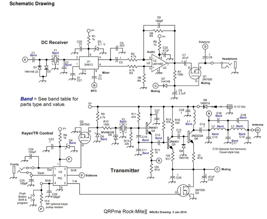
As a reminder, here is the whole schematic for the RockMite.

Schematic for the RockMite transceiver (from QRPMe.com)
Figure 1. The Schematic for the RockMite Transceiver
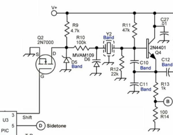
The part of the schematic we need to analyze for this article is near the word “Transmitter” in the big schematic. I’ve cut it down in the next figure (and removed some of the distracting elements).

Figure 2. The RockMite Oscillator
Colpitts Oscillator
The RockMite has within it a Colpitts oscillator. The transistor Q4 is the amplifier and the two capacitors C10 and C11 form the voltage divider. This design employs a crystal (Y2) that is band-dependent, of course, as are C10, C11, and C12. The output of C12 leads to another layer of transistor amplification that enlarges the voltage swing.
Note point B between R13 and R14. This signal leads to the input of the mixer U1 and serves as the beat frequency oscillator (BFO) that detects the received signal.
Silicon Tuning Diodes
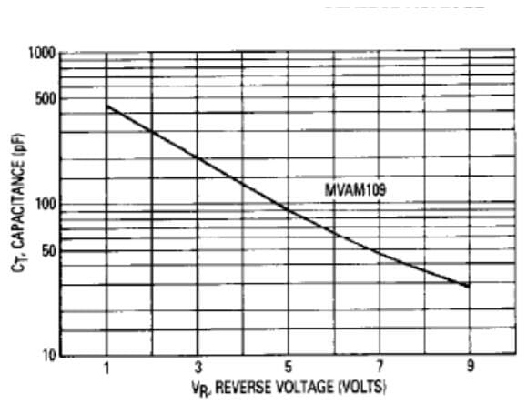
Before I can describe the rest of the circuit I need to introduce a part that I thought was almost magical when I learned about it. The part number for these devices is MVAM109 (in the center of Figure 2). The symbol looks like a cross between a diode and a capacitor. Indeed this is exactly what this part is: a diode and a capacitor combined in a very special way. The varactor (tuning) diode acts like a capacitor, but the capacitance depends on the reverse voltage across the diode. I’ve included a plot from the Motorola data sheet below.

Figure 3. Capacitance versus reverse voltage
You can see that as the reverse voltage goes up the capacitance exhibited by the part goes down. Change the voltage and you change the capacitance. We use this in the part of the circuit described in the next section.
Tuning One of Two Frequencies
The oscillator uses Y2 (a crystal) to help determine the frequency. But, the frequency can be altered by adding or subtracting capacitance. MVAM109 (D6) will be the device that changes the capacitance.
Examine the circuit beginning with Q2 (2N7000). When the transistor is turned on there is a completed circuit between the source and drain (S and D in the diagram). In this case, the source is connected to ground. So, when the transistor is turned on the point in the circuit after D is brought down to zero volts.
Check out R9, a 4.7K Ohm resistor that connects to the drain of Q2, and to a Zener diode D5 (which is also band dependent, as it turns out). The Zener is used as a voltage regulator. Say the Zener is a 3.9-volt model. Since we are connected (through R9) to V+, the voltage at the point where D5 connects to R9 will be limited to 3.9 volts (or whatever the Zener is rated) and R9 is the current limiting resistor. This is assuming the transistor switch Q2 is open (not conducting).
In this situation we have D6 being reverse-biased to the voltage determined by the Zener diode. That much reverse bias will cause the varactor to exhibit some amount of capacitance.
If the switch Q2 is closed (and it conducts) then that point in the circuit is brought down to zero volts and the varactor is no longer reverse biased (or to a voltage below what the D5 part would supply) and we get a completely different capacitance.
The gate of Q2 is controlled by the UI PIC from a line called “Shift”, and it is used to switch between these two frequencies (by turning Q2 on or off). This is how the RockMite offers two different crystal-controlled frequencies with the push of a button.
Next Time
We have already gone through three-quarters of the schematic of the RockMite. Next time, in the last installment, I will walk through the transmitter and the filtering used by the radio.
May 30, 2019


